Fixed Dock Leveler Selection & Maintenance Guide
In the logistics equipment industry, the fixed hydraulic dock leveler is one of the most frequently used yet most underestimated pieces of equipment in loading bay operations. Maintenance technicians, fleet managers, and procurement personnel tend to start paying serious attention only after problems have already surfaced. This guide works through selection criteria, installation details, operation, and maintenance in a structured way — so decisions can be made with confidence.
How a Fixed Dock Leveler Works and Why It Matters
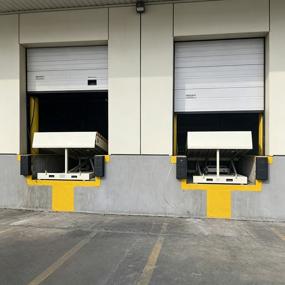
The hydraulic dock leveler creates an adjustable-height load-bearing ramp between the warehouse floor and the truck bed. The standard installation method embeds the unit into a pit cut into the loading bay — this is what the industry refers to as a pit mounted dock leveler. When not in use, the deck plate sits flush with the floor. During operation, the hydraulic system raises the deck and extends the lip plate to bridge the gap with the truck bed.
“A properly specified dock leveler system is not just a steel ramp — it is a complete solution that absorbs the height difference between a fixed platform and whatever vehicle pulls up to it.”
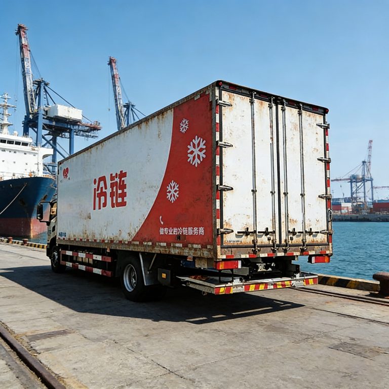
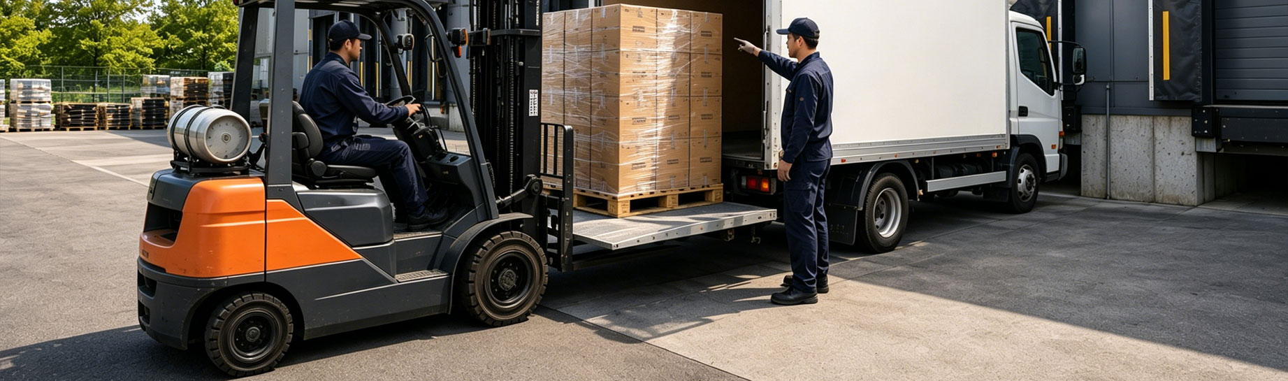
Forklifts travel directly into the truck via the forklift loading dock ramp, eliminating manual handling at the transfer point. In a mid-sized cold chain warehouse, installing a warehouse dock leveler typically reduces unloading time for the same cargo volume by 30% to 40%, with a corresponding reduction in labor costs.
Typical application environments include:
- Manufacturing plants and finished-goods warehouses
- Logistics distribution centers and third-party storage facilities
- Specialized facilities such as grain stores, cold storage, and hazardous materials warehouses
- High-throughput transit hubs including ports and freight terminals
Five Main Structural Components
A complete industrial dock leveler is built around five core structural elements. Understanding what each component does is the foundation for reading product specifications intelligently.
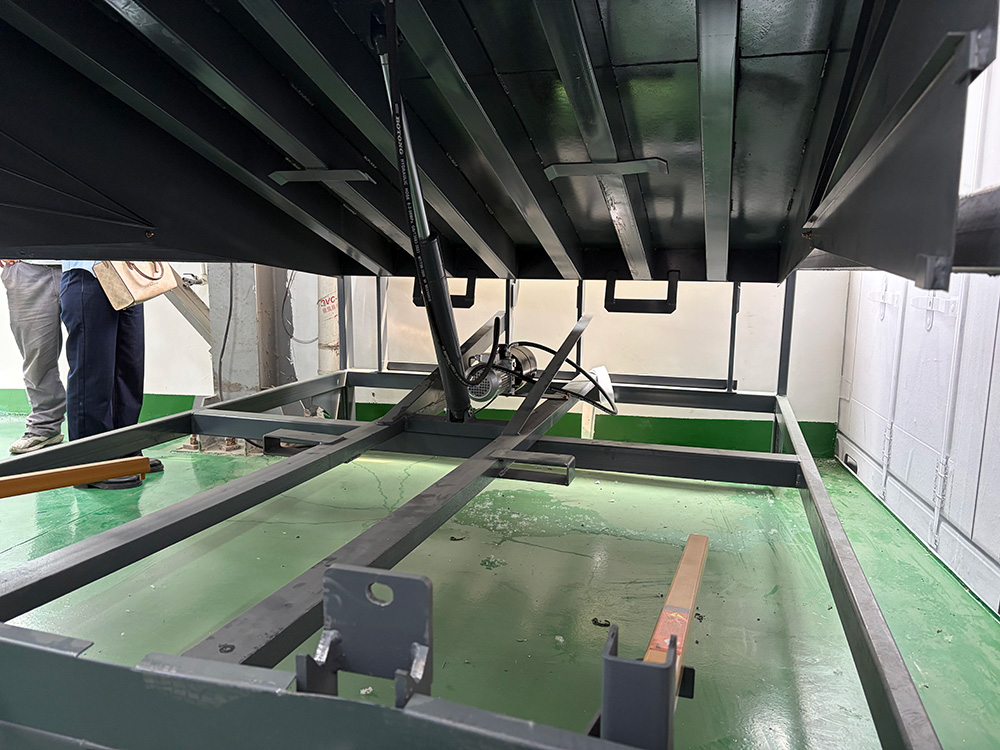
Base Frame
The base frame is the structural foundation of the entire unit, fixed into the pit with concrete anchoring. The rigidity of the base frame directly determines overall stability under heavy load. During installation, the leveling tolerance of the base frame must be kept within allowable limits — if the frame is off-level, the deck plate will experience uneven loading forces and wear unevenly over time.
Deck Plate
The deck plate is the primary load-bearing surface that forklifts travel across. Standard plate thickness is 8mm. This specification reflects a balance between structural strength and overall unit weight. Insufficient thickness leads to mid-span deflection after extended use, which compromises forklift ride quality and accelerates fatigue at the hinge points. The deck surface is typically finished with anti-slip checker plate; in high-cycle heavy-forklift environments, the wear condition of this surface should be checked regularly.
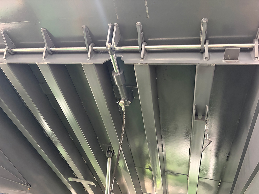
Lip Plate
The lip plate — sometimes called the tongue plate — is the extendable front section of the deck that reaches out and rests on the truck bed. Standard lip plate thickness is 14mm, noticeably heavier than the deck plate itself. The reason is the stress profile: when a forklift crosses the transition point, concentrated loads act at the lip plate root on every pass. The 14mm specification is a structural response to this fatigue loading pattern.
When the lip plate is in the closed position, the overall length of the unit is referred to as the closed dimension. For the most common 6×8 foot size (1830mm wide × 2430mm long), the closed dimension is 2280mm — a figure that matters for pit design and shipping logistics.
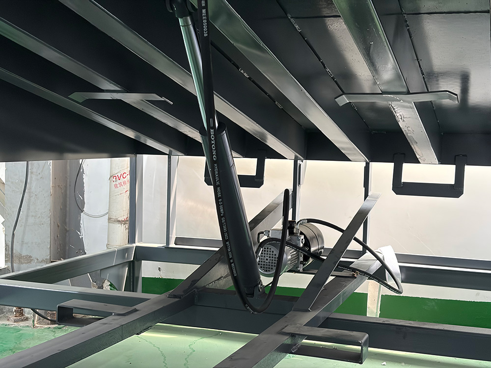
Hydraulic Cylinder
The hydraulic cylinder is the actuator that drives the deck plate up and down. Cylinder stroke directly determines the height adjustment range. The standard stroke specification is: +400mm above level / −300mm below level, giving a total adjustment range of +400/−300mm from horizontal.
Some products on the market are promoted with a ±300mm stroke. Both specifications are valid, but for loading bays where the height differential between the platform and vehicle bed is on the larger end, the +400/−300mm product provides more working margin.
Power Unit
The power unit comprises the hydraulic pump station, control valve assembly, and electrical control box — the operational core of the entire dock leveler system. Standard electrical supply is 220V or 380V AC, 0.75kW, 50Hz. Export projects can be configured for 60Hz supply; the target market’s grid standard must be confirmed before the order is placed, as retrofitting after delivery is both costly and time-consuming.
The standard control box is plastic-bodied and does not include an emergency stop button. Applications with specific safety requirements — hazardous materials warehouses, for example — should specify an upgraded metal control box with emergency stop functionality.
Dimensional Specifications
Deck Width Options
The loading dock leveler is available in three standard widths:
- 1830mm (6 ft) — suits standard single-door truck bays
- 1980mm (6.5 ft) — suits wider door openings or applications requiring more forklift clearance
- 2130mm (7 ft) — for heavy-duty warehousing or wide-body vehicle applications
The highest-volume size in the market is 6×8 feet (1830mm wide × 2430mm long). This format covers the large majority of standard truck configurations and represents the best balance of versatility and cost.
Pit Width Calculation
This is the measurement that causes the most errors during site surveys. The pit width formula for a pit mounted dock leveler is straightforward:
Pit width = deck plate width + 40mm
For a 1830mm-wide deck, the pit should be cut to 1870mm. The 40mm clearance allows the unit to be lowered into the pit cleanly, while keeping the gap tight enough to prevent debris accumulation or foreign objects falling into the space. In retrofit projects on older buildings, always physically measure the existing pit — drawing dimensions and as-built dimensions frequently differ.
Recommended Platform Height
The loading platform height above ground level is recommended to be between 1200mm and 1300mm. This range covers the floor heights of the large majority of commercial trucks operating in standard logistics networks. A warehouse loading ramp with standard stroke installed at a platform in this height band will typically work across the full range of vehicles without needing additional modifications to either the platform or the vehicles.
If an existing platform sits outside this range, the stroke margin available must be calculated carefully before confirming the specification.
Fork Pockets: A Safety Detail That Cannot Be Overlooked
The base frame of a loading dock ramp has fork pockets at both the front and the rear. These two sets of pockets serve entirely different purposes, and confusing them causes equipment damage:
- Front fork pockets are for installation use only — they are used to position the unit into the pit during initial setup. Once the unit is in place, the front fork pockets serve no further handling function. Under no circumstances should the front fork pockets be used when stacking or relocating the unit — doing so will deform the base frame structure.
- Rear fork pockets are for transport and in-warehouse relocation. These are the correct handling points for all routine movement.
This distinction must be clearly communicated to site operators and receiving personnel at the time of handover. Damage caused by front-pocket misuse is a recurring issue in the field and is not covered under standard warranty terms.
Installation: Details That Determine Long-Term Performance
Pit Construction Standards
The pit construction quality for a warehouse dock leveler directly affects service life. Concrete grade at the pit base should be C30 or higher. All four walls require waterproofing treatment. A drain channel or drainage holes at the pit base are essential — standing water corrodes hydraulic components from below. After the base frame is set, secondary grouting locks the unit in position and eliminates any rocking under load.
Hydraulic Line Routing
Hydraulic hose runs and control wiring paths need to be planned before installation is finalized. If these are routed without considering future access, the first maintenance visit often requires removing structural components just to reach serviceable parts. This is one of the most common installation shortcomings seen in the field, and it adds significant time and cost to every subsequent service call.
Safety Interlock Commissioning
A compliant loading and unloading dock solution must include wheel chocks or a vehicle restraint system to prevent the truck from moving while forklift operations are underway. The interlock logic should enforce the following: the deck plate cannot be raised until the vehicle is secured; when the vehicle restraint is released, the control box must trigger an audible and visual alarm. These interlocks must be fully tested and confirmed functional before the installation is signed off.
Maintenance: The Real Determinant of Service Life
The majority of failures in truck loading dock platform equipment — well over 70% — occur in the hydraulic system and sealing components. Nearly all of these are preventable with a disciplined maintenance schedule.
Recommended maintenance intervals and actions:
- Daily inspection: Visual check of the deck plate and lip plate for deformation; check hinge weld seams for cracking; confirm hydraulic fluid level is within the marked range on the reservoir.
- Monthly service: Check hydraulic fluid condition — fluid that has turned black or shows signs of emulsification must be replaced immediately. Lubricate all hinge pins and lip plate pivot points with lithium grease or the lubricant specified in the equipment manual.
- Quarterly inspection: Test all safety interlock functions to confirm correct triggering. Inspect seal condition for signs of aging — in northern regions with cold winters, low temperatures accelerate rubber deterioration and replacement intervals should be shortened accordingly.
- Annual overhaul: Hydraulic cylinder bore inspection, control valve assembly cleaning, and reapplication of corrosion protection coating on structural members. This work should be carried out by qualified technicians.
For dock leveler for warehouse logistics installations, maintenance costs tend to peak between years three and five of service life — this is when seals and hydraulic hoses collectively reach the end of their design life. Keeping a spare parts inventory reduces unplanned downtime significantly.
Common faults and diagnostic starting points:
- Deck raises slowly or cannot reach rated height: Check hydraulic fluid level and pump condition first; then inspect the relief valve pressure setting.
- Lip plate fails to fully extend: Usually caused by seized lip plate hinges or a weakened return spring. If cleaning and lubrication do not resolve the issue, the spring assembly needs replacement.
- Deck slowly sinks on its own: Internal cylinder leakage or check valve seal failure — requires cylinder teardown inspection or valve block replacement.
- Control box alarm will not reset: Start with the vehicle restraint sensor wiring; then check whether supply voltage to the control board is stable.
Configuration Recommendations by Industry
Cold Chain Warehousing
Low-temperature environments have a significant effect on hydraulic fluid viscosity. Specify a low-temperature hydraulic oil with a pour point no higher than −30°C, and consider adding an electric heating element to protect the pump station during cold starts. Sealing components in the loading dock leveler should be specified in low-temperature rubber compounds to prevent cold-weather embrittlement and cracking.
Hazardous Materials Warehouses
Industrial dock levelers in hazardous materials facilities must meet explosion-proof requirements. The control box, motor, and all sensors must carry appropriate Ex-rated certifications. Anti-static checker plate on the deck surface is recommended, and ground resistance should be tested periodically to prevent static charge buildup. The standard plastic control box is not suitable for this environment — an explosion-proof metal enclosure with emergency stop is required.
High-Cycle E-Commerce Fulfillment Centers
In e-commerce warehouse environments, a dock leveler system may see 80 to 120 operating cycles per day — far above the cycle rates of a typical manufacturing facility. Specify heavy-duty rated units for these applications, and require the supplier to provide written documentation of the cylinder and seal design life. The standard 0.75kW motor on the power unit can run hot under sustained high-cycle loading; adding forced-air cooling or specifying a higher-rated motor may be appropriate for the most demanding installations.
Procurement Checklist: Points That Often Get Missed
- Power supply specification: Domestic standard is 50Hz. Export projects must confirm the destination grid frequency before the order is placed — post-delivery modification is expensive and avoidable.
- After-sales service coverage: Can the supplier respond on-site within 48 hours? Are spare parts stocked locally or sourced from distant warehouses?
- Parts interchangeability: Some manufacturers use proprietary hydraulic components not available on the open market. If the product line is discontinued, repairs become very difficult.
- Warranty clause detail: Clarify exactly which failure modes are covered under warranty and which are classified as operator-induced damage — this needs to be written into the contract, not left as a verbal understanding.
- Civil works responsibility: Some suppliers quote equipment only, excluding pit construction. Confirm scope clearly before signing, or unexpected civil costs will appear after delivery.
Summary and Next Steps
This guide has covered the fixed hydraulic dock leveler from structural components and dimensional specifications through selection logic, installation requirements, and daily maintenance — the full picture that procurement and maintenance decisions need to be made on solid ground.
A few points in this article worth particular attention:
- The breakdown of all five structural components gives readers a genuine understanding of what the specification numbers mean, rather than comparing units on a single load rating figure
- The pit width formula (deck width + 40mm) and recommended platform height range (1200mm to 1300mm) are field-ready reference figures that can be taken directly into a site survey
- The fork pocket misuse warning addresses a real and recurring cause of equipment damage that is consistently underemphasized at the point of handover
- The industry-specific configuration advice for cold chain, hazardous materials, and high-cycle fulfillment covers the three scenarios where generic cargo loading dock equipment specifications most frequently fall short
For teams currently evaluating a loading bay upgrade or dealing with a warehouse dock leveler that has been generating repeated faults, the Beauway team is available to help. With a sustained commitment to quality and customer service, Beauway is dedicated to providing every client with a lifting and docking solution that genuinely fits their operational requirements. Contact the Beauway team for tailored dock leveler selection advice and complete product documentation.