Having trouble submitting? Email us directly at nicole@beauway.com and we'll get back to you within 24 hours.











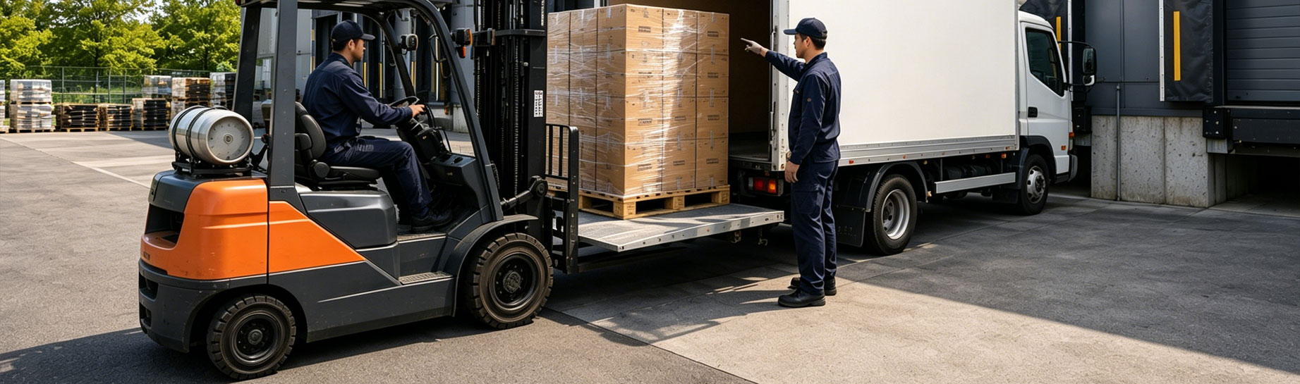
How Does a Tail Lift Work? The Hydraulic Lifting Mechanism Explained
How does a tail lift work? An electric motor drives a pump. The pump pressurizes hydraulic oil. That pressurized oil pushes a cylinder, and the cylinder raises or lowers the platform. A mechanical linkage keeps the platform level as it moves. A safety valve stops the platform from falling if the system loses pressure. That’s the short version of how a tail lift works. The rest of this article breaks down each part of that system and explains why engineers build it this way.
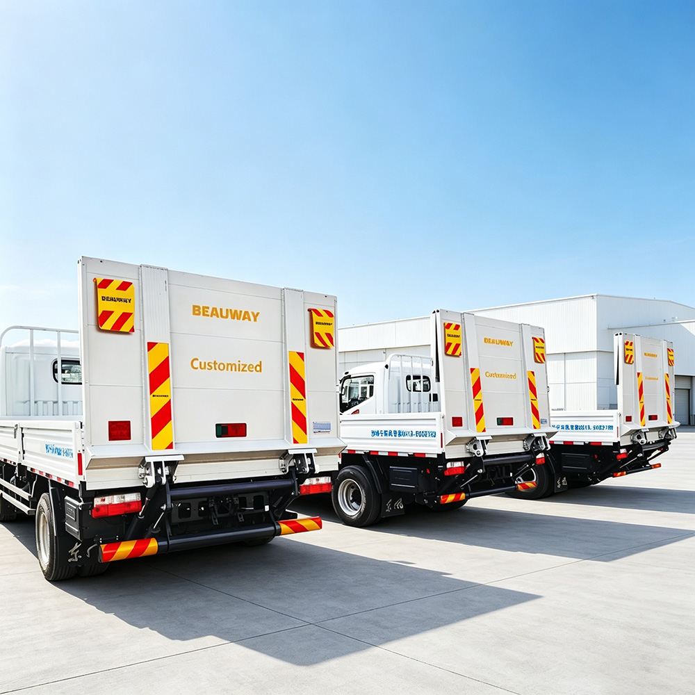
How Does a Tail Lift Work, Structurally?
A tail lift is a powered platform mounted at the back of a commercial vehicle. It bridges the height gap between the ground, or a loading dock, and the vehicle bed. Goods move on and off without anyone lifting them by hand. That’s the plain-language version of tail lift meaning.
Mechanically, a tail lift is a small hydraulic machine. It combines four parts: a power source, a fluid circuit, a mechanical linkage, and a set of interlocks. Together, these parts keep the system predictable under load.
The Four Building Blocks
Almost every hydraulic tail lift on the road today uses some version of these same four blocks. Builders wire and plumb them together differently depending on the vehicle and the load rating. A control box or pendant handles the electrical side: it sends a signal to the motor when the operator presses raise or lower. The hydraulic and mechanical parts then do the physical work. Once you understand how these pieces connect, a tail lift diagram stops looking like a tangle of arms and hoses. It becomes a simple, traceable chain: power in, force out, motion controlled at every stage.
How Does a Tail Lift Work Inside the Hydraulic System?
The lifting force doesn’t come from a motor pulling a cable. It doesn’t come from a screw turning a gear, either. It comes from pressurized fluid pushing on a piston — the same physics as a car jack, just scaled up and automated.
The Core Hydraulic Loop
The loop works in four steps:
- An electric motor — 12V on light vehicles, 24V on heavier-duty applications — drives a hydraulic tail lift pump. The pump draws oil from a reservoir.
- The pump pressurizes that oil and pushes it toward a control valve.
- The control valve routes the pressurized oil into one side of a hydraulic cylinder. It sends oil to the other side when the operator reverses direction.
- Inside the cylinder, pressurized oil pushes a piston. The piston connects to a rod, and the rod connects to the arm structure that carries the platform.
The force this loop produces follows a simple rule: pressure multiplied by the piston’s surface area equals the lifting force. Double the pressure, or double the piston’s cross-section, and the available force roughly doubles too. A heavier-duty lift rarely relies on a “stronger” motor alone. Engineers usually pair it with a larger-bore cylinder, a higher system pressure, or both, matched to the rated load.
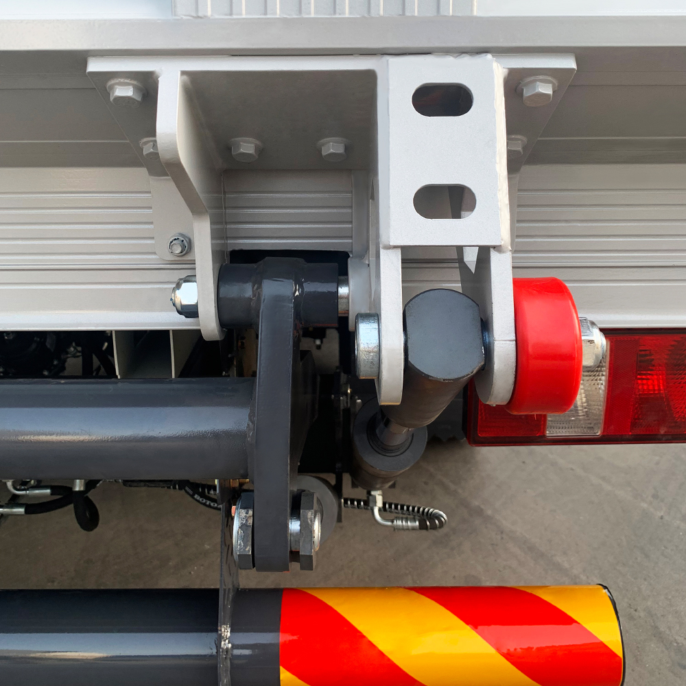
Why Tail Lift Hydraulic Oil Matters
Tail lift hydraulic oil isn’t interchangeable with any hydraulic fluid on a shelf. The oil has to stay stable across a wide temperature range. It also has to resist wear inside the pump and valves over tens of thousands of cycles. For these reasons, manufacturers specify a particular viscosity grade. Cold-climate operations typically need a thinner grade than standard conditions call for. An oil that’s too thick for the weather often causes sluggish response on a cold morning — even when every mechanical part underneath works fine.
Single-Acting vs. Double-Acting Cylinders
Not every cylinder in this system works the same way. A single-acting cylinder takes pressure on only one side. Oil pushes the piston out; gravity, a spring, or the platform’s own weight brings it back. A double-acting cylinder takes pressure on both sides, so oil actively pushes the piston in both directions.
Double-acting designs generally give smoother, more consistent movement in both directions. That matters most on heavier platforms, where descent speed shouldn’t depend on how much weight sits on the platform at any given moment. Single-acting designs stay mechanically simpler and need fewer seals over the lift’s service life. That’s part of why manufacturers still choose them for lighter-duty applications.
The Parallelogram Linkage: Keeping the Platform Level
A hydraulic cylinder only pushes in a straight line. On its own, that motion would tip the platform as it travels, rather than raising it evenly. The mechanical structure around the cylinder — not the hydraulics — does the real work of controlling the platform’s angle.
Two Arms, One Constant Angle
Most designs use a parallelogram arm arrangement. Two arms of equal length, mounted at equal spacing, connect the platform to the vehicle frame. Opposite sides of a parallelogram always stay parallel to each other, no matter how the shape stretches or compresses. This geometry keeps the platform’s angle constant as it travels between ground level and the truck bed. The linkage does the geometric work of holding that angle steady — not the operator, and not the hydraulics.
Why Two Cylinders Need to Move Together
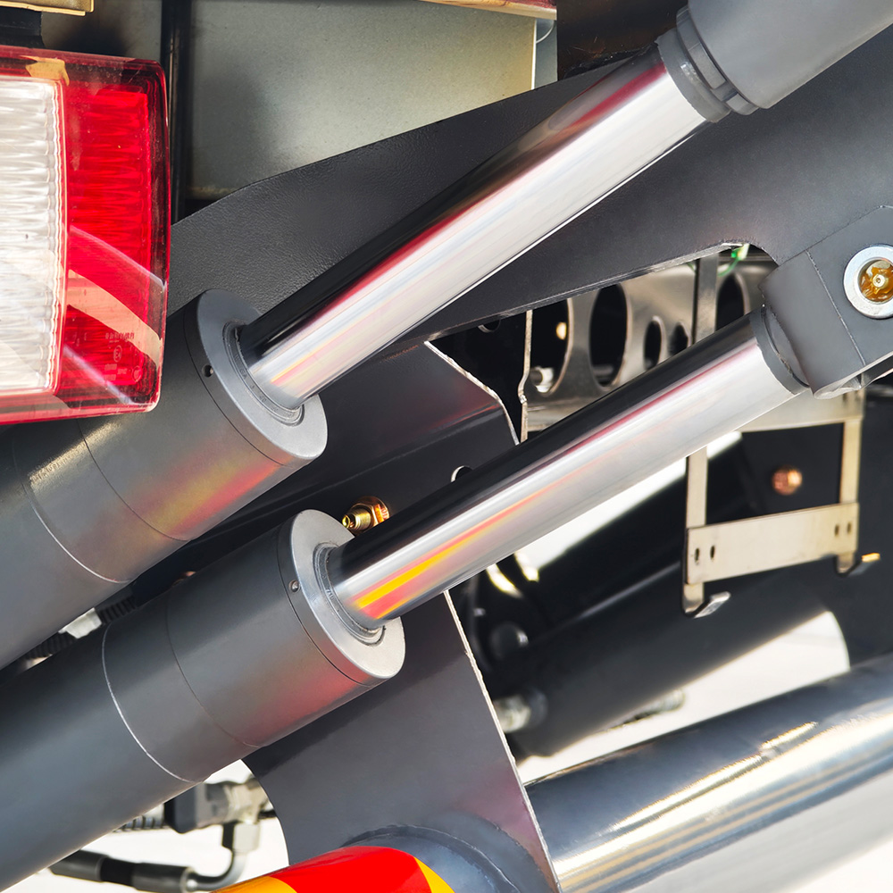
Wider platforms need more than one cylinder to carry the load evenly, so the lift uses two — one per arm. That creates a coordination problem. If the two cylinders extend at even slightly different rates, the platform tilts sideways instead of moving through a level plane. Engineers solve this two ways. Some designs route hydraulic flow through a flow divider valve, which splits pressure evenly between both cylinders. Others add a mechanical crossbar or torsion element between the arms, forcing them to move together no matter how the pressure balances on each side. Either approach works. But this synchronization detail often gets overlooked, and it’s usually the first thing that shows up as a visible problem: a platform that leans slightly to one side under load.
The Safety Mechanism: What Stops the Platform From Falling
Everything above explains how the platform moves under normal power. Just as important: what happens when it loses power? Specifically, what stops a loaded platform from dropping if a hose bursts or a seal fails mid-lift?
The Anti-Drop Valve
A component called an anti-drop valve, or balance valve, answers that question. Engineers fit it directly at the cylinder. Under normal operation, this valve simply lets oil flow in and out as the lift raises and lowers. But engineers design it to close the moment supply-side pressure drops suddenly — exactly what happens when a hose ruptures. Once closed, the valve blocks oil from flowing back out of the cylinder. The trapped oil holds the platform in place, even after the pump loses pressure entirely.
This single valve counts as the most important safety component on any hydraulic tail lift platform. It has to work correctly at the exact moment everything else has already failed. A pressure sensor can warn an operator about an overload before it happens. A mechanical lock can hold the platform steady during transit. But only a properly rated anti-drop valve handles a sudden, mid-lift loss of hydraulic pressure.
Other Interlocks Worth Knowing
Beyond the anti-drop valve, a complete system layers on a few more interlocks. Each one covers a different failure scenario:
- Mechanical locks hold the platform in its stowed position during transit, independent of the hydraulic system.
- Limit switches stop the lift automatically at the top and bottom of its travel range, protecting the cylinder from over-extension.
- Roll stops sit at the platform’s edges. This raised lip keeps wheeled loads, like pallet jacks or trolleys, from rolling off during transfer.
None of these components does the same job as the others. The system’s overall safety depends on all of them working together, not on any single device carrying the full load.
How Structural Design Changes the Mechanism
The core lifting principle — pump, valve, cylinder, linkage — stays the same across almost every design. But the surrounding structure changes based on how the platform needs to stow when not in use. Some platforms fold upward against the rear doors, prioritizing a compact footprint over ground clearance. Others tuck fully underneath the vehicle bed, keeping the rear doors completely clear. A third common arrangement runs the platform up and down a pair of vertical guide columns instead of swinging it on an arm. Builders use this design where the lift needs to sit flush and low when stowed. The hydraulic loop and the safety valve stay conceptually identical across every arrangement. What changes is the geometry of the arms or columns carrying the platform, and how much stowed space that geometry needs.
Why the Control System Matters as Much as the Hydraulics
The electrical control box looks like an afterthought bolted onto the hydraulics. It isn’t. On most modern lifts, the control system enforces the limits that keep the mechanism from damaging itself. It cuts power when the platform reaches the top or bottom of its travel. It blocks movement commands while a safety interlock stays engaged. Some systems even log fault codes, which speeds up troubleshooting later.
A worn switch or a corroded connector here produces symptoms that look just like a hydraulic problem — the platform simply won’t move. Yet the pump, oil, and cylinder might all work correctly. That overlap explains why a proper diagnostic sequence always checks the electrical side first, before anyone assumes the hydraulics have failed.
How to Tell If the Hydraulic System Is Wearing Out
Most hydraulic problems show up gradually, through seal wear rather than sudden failure. A simple test catches this without any tools. Raise the empty platform to roughly waist height. Leave it alone — don’t touch the controls — for about 60 seconds. A well-sealed cylinder holds that position with barely any movement. If the platform sinks more than a few millimeters in that time, oil is bypassing the piston internally. That points toward worn seals, not a problem with the fluid or the pump. A wet film or visible oil residue on the piston rod signals the same underlying issue. Neither check requires opening the hydraulic system. Both just require watching it closely for a minute.
Frequently Asked Questions
Q: What is a tail lift?
A: A tail lift is a hydraulically, or occasionally mechanically, powered platform mounted at the rear of a commercial vehicle. It raises and lowers goods between ground level and the vehicle bed.
Q: How does a tail lift work, in one sentence?
A: A motor drives a pump that pressurizes oil, a valve directs that oil into a cylinder, and the cylinder — guided by a parallelogram linkage — raises or lowers the platform, while an anti-drop valve prevents it from falling if pressure is lost.
Q: Why does a tail lift need a parallelogram arm instead of a single arm?
A: A single arm would tilt the platform as it travels. A parallelogram arrangement keeps the platform at a constant angle across its full range of motion.
Q: What actually stops the platform from falling if a hose bursts?
A: An anti-drop, or balance, valve fitted directly at the cylinder does. It closes automatically the moment it detects a sudden pressure loss, trapping oil inside the cylinder and holding the platform in place.
Q: Does the hydraulic oil in a tail lift actually matter?
A: Yes. The oil has to match the viscosity grade the system was designed around. The wrong grade — particularly one that’s too thick for cold weather — commonly causes sluggish or delayed response.
Summary: How Does a Tail Lift Work, In Short
A truck hydraulic tail lift comes down to a short, logical chain. A motor drives a pump. The pump pressurizes hydraulic oil. A control valve routes that oil to a cylinder. The cylinder — kept level throughout its travel by a parallelogram linkage — moves the platform. A set of safety components sits on top of that motion, led by the anti-drop valve. Its entire purpose: behave predictably at the exact moment the hydraulic system doesn’t. Understanding that chain does more than answer how does a tail lift work as a curiosity. It’s also the fastest way to spot what’s actually happening when something goes wrong — and which part of the system to check first.
Trusted by Fleet Operators Across 60+ Countries
Stop Losing Time at the Loading Dock.
Get a Custom-Matched Tail Lift Quote in 24 Hours.
60
Countries Served
24h
Quote Turnaround
99.9
Field Uptime
5.0
Customer Rating
No Obligation
CE & UKCA Certified
Standard & Custom Builds
Worldwide Shipping