Hydraulic Tail Lift Power Unit Components and Working Principle Explained
Overview
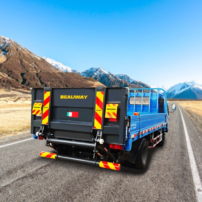
The automotive tail lift hydraulic power unit (Tail Lift Hydraulic Power Unit) is the core hydraulic source used in cargo loading and unloading systems. It provides stable power for lifting, lowering, and tilting operations of the tail lift, directly influencing logistics efficiency and operational safety.
In commercial vehicle applications, this system is also commonly referred to as a hydraulic power pack for tail lift or an independent hydraulic power module (Tail Lift Power Unit), depending on regional engineering documentation standards.
System Configuration and Structure
The system is generally built around three main subsystems: power drive, hydraulic control, and oil storage with auxiliary functions.
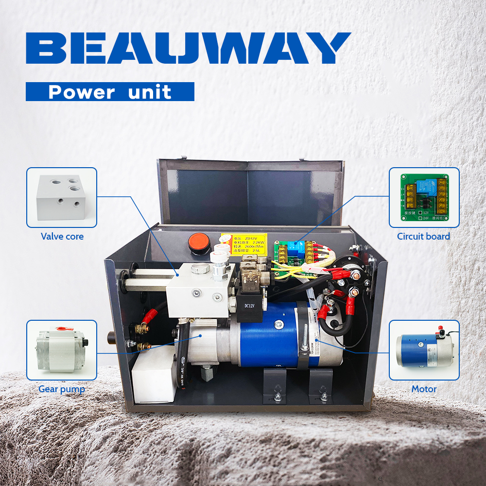
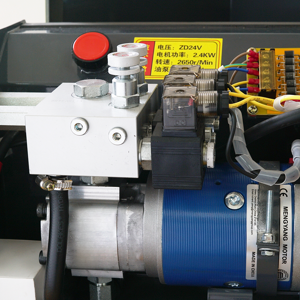
Power Drive Unit
Core components include:
- DC Motor, powered by the vehicle battery and responsible for initiating mechanical drive
- High-Pressure Gear Pump, converting mechanical energy into hydraulic energy and generating system pressure
Together, these form the basic energy conversion stage of the entire hydraulic system. In practice, this is the point where electrical input begins to become usable hydraulic force.
Hydraulic Control Unit
Main components include:
- Manifold Block (Hydraulic Valve Block), responsible for organizing multi-path hydraulic flow and distribution logic
- Hydraulic Control Valves, used for switching flow direction and regulating system pressure
The manifold acts as the central routing structure of the hydraulic circuit, while the valves respond directly to operational commands during lifting and lowering actions.
Oil Storage and Auxiliary Systems
| Component | Function | Technical Description |
|---|---|---|
| Hydraulic Oil Tank | Stores hydraulic oil | Hydraulic oil reservoir |
| Filter | Removes contaminants | Filtration unit for system protection |
| Pressure Gauge | Monitors system pressure | Real-time pressure feedback device |
| Breather | Balances internal pressure | Prevents tank deformation under pressure changes |
These elements do not directly generate power, but they are essential for maintaining long-term system stability and reliability.
Operating Principles
Operational Sequence
Operation command → control system → motor startup → gear pump rotation → hydraulic pressurization → manifold distribution → valve switching → cylinder actuation → tail lift movement
This sequence represents the standard working cycle of a tail lift hydraulic system.
Working Process Explanation
When the operator activates the control switch, a signal is sent to the control system, which triggers the DC motor to start running.
The motor drives the gear pump, which draws hydraulic oil from the reservoir and builds pressure.
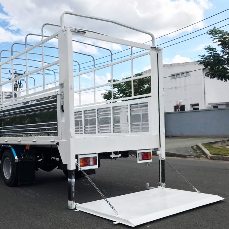
The pressurized oil then flows into the manifold block, where it is distributed to different hydraulic valves. These valves control the direction of flow into the cylinder, allowing the piston to move and complete the lifting or lowering action.
In practical engineering terms, this is referred to as the hydraulic power unit working cycle.
Core Functions
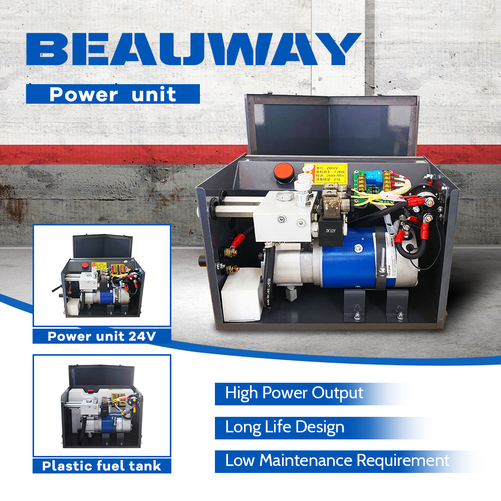
Lifting Power Output
The system provides stable hydraulic pressure to ensure smooth tail lift movement. This is the basic requirement for all standard lifting operations.
Heavy-Load Capability
Due to the nature of hydraulic transmission, the system can handle high load conditions with stable output performance. This is particularly important in heavy-duty transport environments.
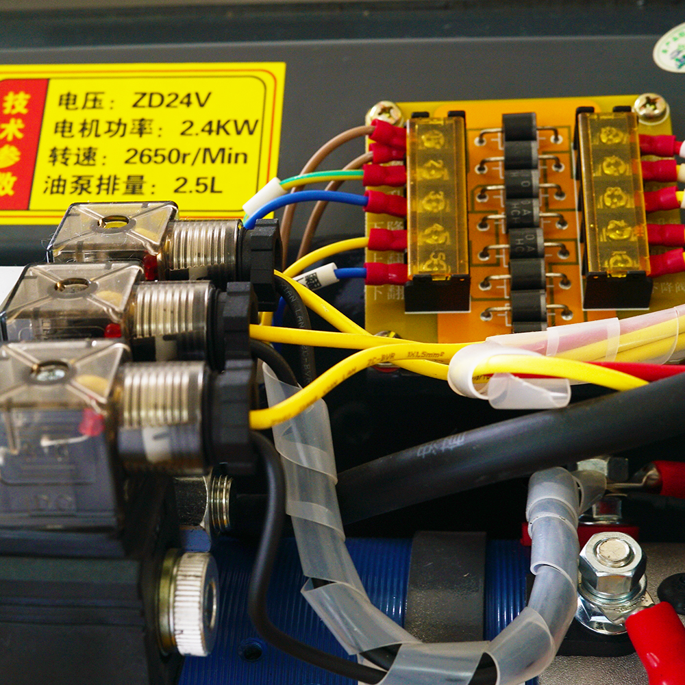
Operation Control System
Modern systems are typically equipped with electric control systems that integrate multiple safety and control functions, including:
- Remote or button-based operation
- Overload protection
- Stroke limitation
- Fault detection and self-diagnosis
Typical Application Scenarios
Tail lift hydraulic power units are widely used in:
| Application Field | English Term | Characteristics |
|---|---|---|
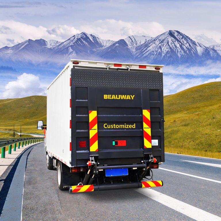
| Logistics Transportation | Logistics Tail Lift System | High-frequency operation requiring stability |
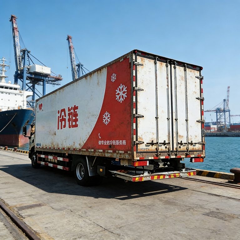
| Cold Chain Transportation | Cold Chain Transport Tail Lift | Low-temperature hydraulic performance requirements |
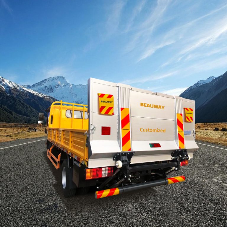
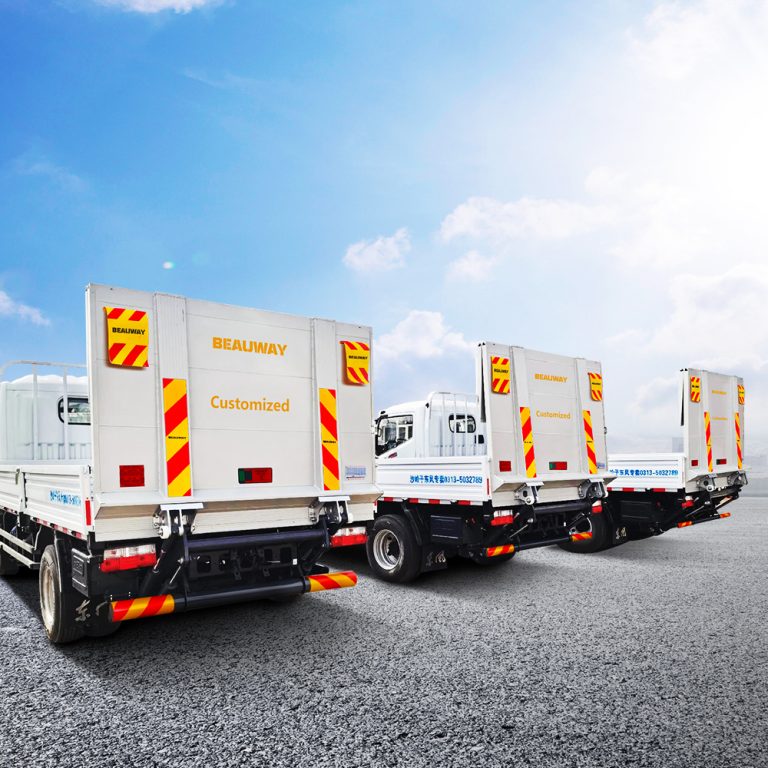
| Cargo Trucks | Truck Tail Lift Equipment | Heavy-duty load conditions |
| Commercial Platforms | Commercial Tail Lift Platform | Multi-environment adaptability |
Maintenance Points and Fault Analysis
System-Level Maintenance Concept
In real-world applications, performance issues are rarely caused by a single component. They are usually the result of combined system factors.
Common issues include:
- Hydraulic oil contamination
- Pump wear
- Solenoid valve sticking
For this reason, diagnosis should always be performed from a complete system perspective rather than focusing on individual parts.
Preventive Maintenance Practices
- Regular replacement of hydraulic oil and filters
- Inspection of motor and pump coupling tightness
- Cleaning of hydraulic valve assemblies
- Monitoring of system pressure trends
- Checking electrical and control connections
Conclusion
The automotive tail lift hydraulic power unit is an integrated system combining motor drive, hydraulic pressurization, and electrical control functions.
Its performance directly determines the efficiency, safety, and reliability of tail lift operations. In practical engineering applications, system-level thinking is essential for both selection and maintenance.